A Programming Language for Logic Circuits
About
Logically is a scripting language that can derive the combinational logic circuit of any logic expression. Given a set of logic operations, the language is capable of analyzing the resulting function and with a series of computations, a logical circuit will be derived.
Introduction
Boolean logic is a branch from algebra in which variables are evaluated with truth tables where said variables have a value of “1” or “0” and certain outcome based on the expression. The operations used for evaluating the logic are OR, AND & NOT. These operations are represented by disjunction(U), conjunction(∩), and negation(-), respectively. With these expressions, it is possible to express and evaluate Boolean Algebra. The following logic can then be used to construct circuits called combinational logic circuits (often referred as logical gates or logic circuits).
These combinational logic circuits can range from very simple ones to very complicated ones. And so, developers use different techniques to specify the function of these combinational logic circuits like Boolean Algebra, Truth Tables and Logic Diagrams. Common combinational circuits made up that carry out a desired application include: Multiplexers, Encoders, Decoders, Half Adders, Full Adders, etc. Logically looks to simplify the process of designing logic circuits and to provide all the necessary tools used when dealing with logical expresions. Instead of spending a lot of time writing tables and karnaugh maps, users can obtain the same results by typing some simple commands.
Language Features
- Design logical circuits by implementing individual logic gates.
- Create complex logical expressions from logic circuits.
- Test circuits by generating truth tables.
- Simplify any logical expression with a single command.
- Generate visual circuit diagrams from generated circuits.
- Display the venn diagram of a given logical expression.
How It Works
The following is a video tutorial on how to install and use Logically.
Program Examples
Example 1: Expression Build, Table Generation and Circuit Drawing
>>out = OR a b
Added Expression to:  out
>>a = AND c d
Added Expression to:  out
>>c = NOT e
Added Expression to:  out
>>b = AND f e
Added Expression to:  out
>>f = NOT d
Added Expression to:  out
>>TABLE out
Generating truth table:

( ( not e ) and d ) or ( e and ( not d ) )
d	e	out
0	0	0
0	1	1
1	0	1
1	1	0
>>CKT out
Generating circuit diagram
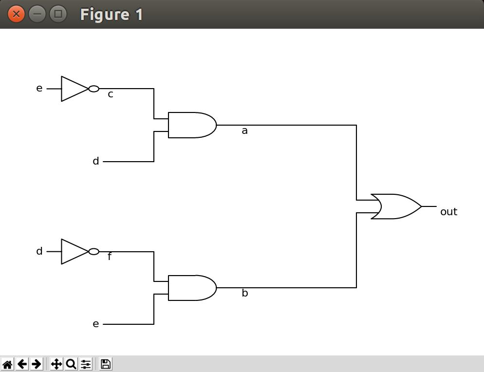
Figure 1: Output from Example 1.
Example 2: Testing the Simplify
>>out = AND x y z
Added Expression to:  out
>>x = AND b c
Added Expression to:  out
>>y = AND c d
Added Expression to:  out
>>z = OR c d
Added Expression to:  out
>>SIMPLIFY out
Simplifying out
( b and c ) and ( c and d ) and ( c or d )
['b', 'c', 'd']
[0, 0, 0, 0, 0, 0, 0, 1]
Result:
 bcd
Example 3: Testing Venn Diagrams
>>exp = OR a x
Added Expression to:  exp
>>x = AND a b
Added Expression to:  exp
>>VENN exp
Generating venn diagram
a or ( a and b )
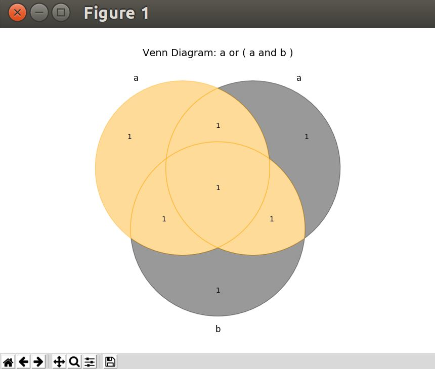
Figure 2: Output from Example 3.
Installation
Dependencies
- Python 3.4 with the following packages:
- SchemDraw
- Matplotlib
- TKinter
- PLY
Instructions
- Download the program to your machine. You can download the code from here
- After downloading the code open a terminal and change to the
Logicallydirectory. - Change to the
logically_exedirectory and runpython logically.py. - Enjoy logically
Developers
The developers of logically are a group of students of the University of Puerto Rico at Mayagüez. The team members are: Jean O. Candelaria, Gustavo A. Hernandez, Yorki G. Serrano and Javier Ramirez. This project was developed as part of the Programming Language course (ICOM4036) directed by Dr. Wilson Rivera.
Final report for the class project can be found at the link in the top of the website or here .